Hi There,
This is Andrey Mikhalchuk and RTFMs video blog, the information you will never find in your regular user’s manual. In this episode we will build a simple robot and program it to solve a maze. The best part of the project is that it will only take about 15 minutes of your time, requires no soldering, no expensive materials and no advanced skills at all.

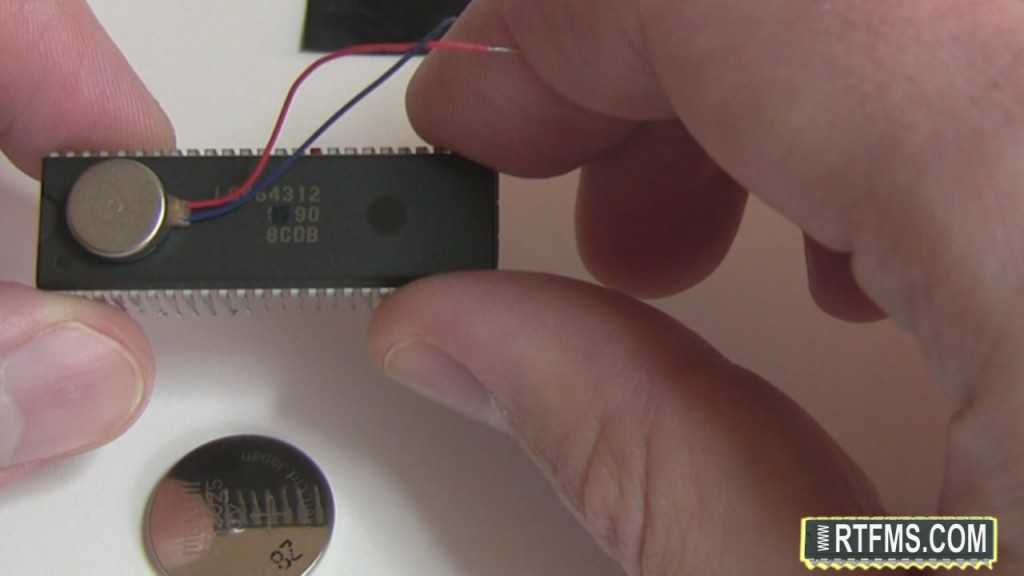
As you probably have heard most simple robots are built around a microcontroller, so our first step will be choosing the right chip. Some people prefer Arduino, some – Basic Stamp, FPGA-based solutions, full-scale PC processors… Well, the good news is that for this project you can choose any of those. For instance I chose LC864312, specifically designed for … Hmmm … I actually have no idea what that chip does and this is exactly why I chose it for this simple project
So pick any chip you like, and let’s proceed with the power source for our robot. You can get one of these 3V coin batteries in any store nearby.
The final piece of hardware we will use is this tiny shiny piece of electromechanics. It looks like a battery, but it is not. It is called a vibration motor. You can find in any cellphone or pager. If you don’t have a cellphone to spare you can get this vibration motor for $5 from Sparkfun Electronics.
Let’s start building our robot with attaching the vibration motor to the microchip. If you got the fresh motor than it should already have the adhesive, just remove the protective film and stick it to the chip. If it doesn’t have the adhesive you can use electrical tape or tiny drop of glue. Just don’t use the double-sided adhesive foam tape as it will significantly reduce the speed of the robot.

Next, use a piece of tape to attach the blue wire of the vibration motor to the battery. Observe the polarity: the red, “positive”, wire should go to the side of the battery marked as “+” and the blue, “negative”, one should go to the other side. Do not attache the red wire to the battery just yet, stick it to the tape.Use the foam tape to attache the battery to the microcontroller. Now if you bend the electrical tape you can use it to stick the red wire to the battery. It effectively works as a power button.

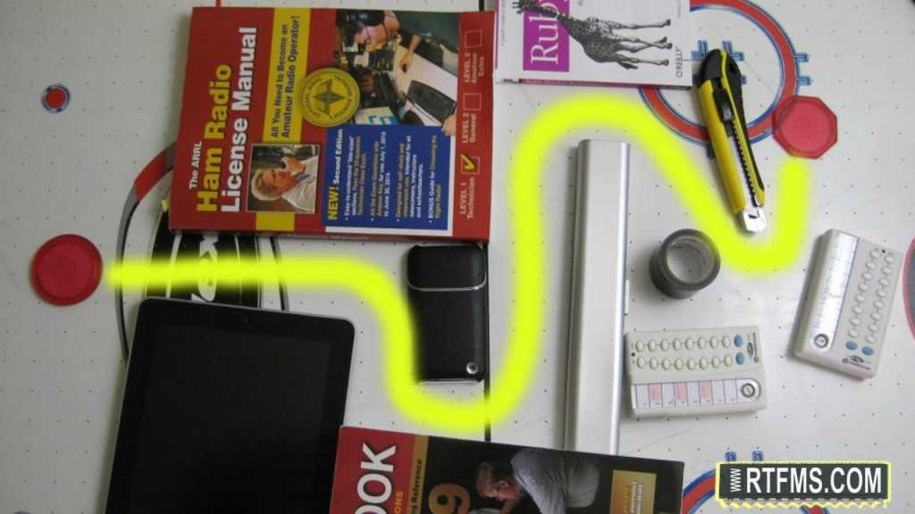
Take a look at the maze we want our robot to solve. It is built in a manner that allows solving it by following the left wall. What we need is to make our robot to follow that rule.
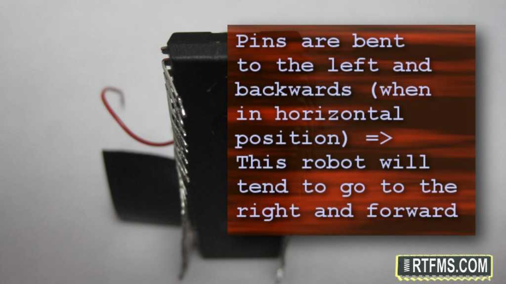
It’s time to “program” our robot. We can easily do it by bending the pins. If you bend the front couple pins to the left it will tend to turn right. If you bend them to the right it will tend to keep left and this is exactly what we need.

Here is the example of right-handed robot in action.
Let’s reprogram our robot to follow the left-hand rule and see how it will work in the maze.
In the following episodes we will be researching and using more sophisticated technologies. I hope this first step in the world of robotics was easy for you.
See You Later!


Good work.
are you a ham.
yeap, ham I am :)
(KR3K)
I am science teacher and appreciate the simplicity of teaching robotics. I would like to see the source code
Thanks
johncap100,
There is actually no source code per se. My idea about this project was making fun of term “programming”. Programming a robot not necessarily should be writing code, robots can be programmed different way too. In this project I actually “programed” this simple robot with pliers by bending the microcontroller pins. I hope it opens mind to non-standard approaches to problem solving. It is also quite educational to see that you can program a basic bristlebot with pliers and make it solve a maze :)
Andrey