Look what I have! This is not computer graphics, the locket is actually glowing with shimmering light constantly changing the color. It looks fantastic, especially in the the evening when only candle lights light up the room, you know. It makes a great present and in this video I will explain how you can build your own. While implementing this project you will also learn all basic things required to program PICAXE-08 microcontroller and find out how to get 3 PWM channels from a microcontroller that has just one.

As you can guess from the name of this episode there is a microcontroller inside the locket that drives an RGB LED. The microcontroller and an RGB LED are responsible for all this light show. For this simple project I chose PICAXE-08.
Why PICAXE-08? Well, this is the simplest beginner-friendly microcontroller out there. It doesn’t require anything sophisticated to program it, it’s cheap, it uses programming language called Basic, which associates with the simplest programming language possible in most people’s minds.
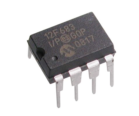
So let’s first program our microcontroller. We will need the following parts:
– the locket itself. Use what you already have, any kind of jewelry with some space available inside. For reference this is what I used: https://www.amazon.com/Sterling-Silver-Filigree-Marcasite-Necklace/dp/B000J4DDH4
– the PICAXE-08 microcontroller itself. Surprisingly you can get this sophisticated piece of microelectronics for about $3!
– a basic breadboard
– 10K resistor and 22K resistor. I recomment you buying a variety pack from Radioshack. It contains dozens of resistors of different nominal.
– either a DB-9 connector or 3 wires to replace it. If you choose to go with wires just twist them around needse on one end so you can connect it to the serial port connector pin. Some heatshrink will make this contact more reliable. DB-9 connector is by far more convenient option though.
– bunch of wires good for breadboard (with solid core, not stranded)
– if your computer doesn’t have a COM port (and I’d be surprised if it is so old that it has one) you will also need a USB-to-RS232 convertor. We already used it in episode #3 to connect voice-controlled robot to the computer and will use it frequently in the future.
– A common-cathode RGB LED. RGB LED is a combination of red green and blue LEDs in single package, so it has 4 wires instead of 2: one common cathode wire and 3 anodes for each color/LED.
There is a variety of RGB LEDs that has just two contacts. It automatically changes color, so in theory you can use that kind of RGB LED and a battery to produce some kind of color effect without the microcontroller. In practice the color changes those LEDs produce is a bit irritating at best.
Everything from the list is available from RadioShack or eBay and should not cost you more than $20 total. Once you get all the parts assemble them according to this diagram:
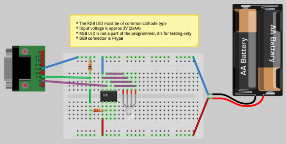
Please note that
* The RGB LED must be of common cathode type, not common anode, not 2-contact one. This is very important
* Input voltage is approx 3V (2xAA). PICAXE-08 specs recommend 4.5V, especially for programming it, but I found it works even from 2.8V (two rechargeable batteries) just fine and you can even program it with this voltage applied.
* RGB LED is not a part of the programmer, it’s for our project only. You don’t have to remove it while programming the microcontroller.
* DB9 connector is F-type (the one with holes, not pins)
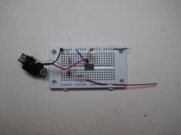
This is how it looks like when assembled (it looks slightly different from what you saw on the breadboard diagram, but electrically it is the same).
Next you need to download PICAXE integrated development environment. This page lists a bunch of them: https://www.rev-ed.co.uk/picaxe/software.htm. Personally I like multiplatform AXEpad, but if you like nice diagrams more than boring text you might prefer PICAXE Programming Editor Software. Both are free for home use. In this video I’ll use AXEpad.

You can write your own programs to implement different visual effects for the RGB LED, but if you’re just starting with microcontroller programming it’s more convenient to start with an example. For instance you can copypaste this code into the IDE window.
 #rem
 Simple PICAXE 08m basic program that randomly and independently controls
 brightness of all 3 colors in a RGB LED
 creating calming patterms (like in a mood lamp).
 See my blog https://andrey.mikhalchuk.com for more details
You're free to do whatever you want with this code, just mention my blog https://andrey.mikhalchuk.com
 in the comments, so people can find updated code. Thanks!
This is my very first program for PICAXE, I apologize if this code doesn't meet your quality
 expectations and harms your feelings about how good code should look like :)
 #endrem
#picaxe 08m
 setfreq m4
; config
symbol SPEED = 3 ; the smaller the value the higher the color change speed
symbol SPEED_VARIATIONS = 7 ; defines how many different color change speeds should it use
; map pins
symbol RED0_PIN = 0
symbol GREEN0_PIN = 1
symbol BLUE0_PIN = 2
; map pin values to mem
; pin value is the current brightness of the LED
symbol red0 = b0
symbol green0 = b1
symbol blue0 = b2
; map pin_deltas to mem
; delta is the speed of the brightness change
symbol red0_delta = b3
symbol green0_delta = b4
symbol blue0_delta = b5
; temp values for the subroutine
symbol delta_w = w3
symbol tmp = b7
; subroutine parameters
symbol pin = b8
symbol val = b9
symbol delta = b10
; initialize everything
red0 = 0
green0 = 70
blue0 = 200
red0_delta = 1
green0_delta = 5
blue0_delta = 9
; start servo mode
; note that "servopos RED0_PIN, 255" renders LED off!!
; "servopos RED0_PIN, 0" makes it really dim, but lit. Is that a bug in PICAXE?
servo RED0_PIN, 255
servo GREEN0_PIN, 255
servo BLUE0_PIN, 255
; this code is like loop() in arduino
main:
; emulating function call in function-less environment
pin = RED0_PIN : val = red0 : delta = red0_delta : gosub set_color_val : red0 = val : red0_delta = delta
pin = GREEN0_PIN : val = green0 : delta = green0_delta : gosub set_color_val : green0 = val : green0_delta = delta
pin = BLUE0_PIN : val = blue0 : delta = blue0_delta : gosub set_color_val : blue0 = val : blue0_delta = delta
goto main
; this sub adjusts the brightness of the LED and delta
set_color_val:
val = val + delta
if delta < 128 and val < delta then ; fwd
random delta_w
delta = delta % SPEED_VARIATIONS + 1
delta = 255 - delta
val = 255
elseif delta >= 128 and val >= delta then ; reverse
random delta_w
delta = delta % SPEED_VARIATIONS + 1
val = 0
endif
tmp = val - 1 ; servopos bug workaround
; yeah, servopos takes only constant as the first argument :(
if pin = RED0_PIN then
servopos RED0_PIN, tmp
elseif pin = GREEN0_PIN then
servopos GREEN0_PIN, tmp
elseif pin = BLUE0_PIN then
servopos BLUE0_PIN, tmp
endif
pause SPEED
return
; see my other blog https://rtfms.com and video blog RTFMs on youtube for demo
 ; this is covered in episode #7: Microcontroller Meets Jewelry
What’s cool about this code is that it drives RGB LED and independently dims every color. Typically this is achieved by using PWM (Pulse Width Modulation) and most microcontrollers have special hardware to produce PWM signal. PICAXE-08 also has this capability, but it is only available on one channel. So this program generates PWM signal for three colors software way.
If you have experience with LEDs you might also wonder where are the current limiting resistors in this device? Well, they didn’t fit into the package, so I didn’t install them :) Is that bad? Well, this particular setup operates on 2.8-3.3V (3.3V is provided by fresh batteries, 2.8V by old ones). For blue and green subLEDs this is totally fine. Red one however works on 2.3V max, 20mA. So in theory it could burn out. However in practice this is not happening because the rates I mentioned are for 100% duty cycle work. We’re driving it with PWM, and it only reaches full brightness for very short periods of time. This particular LED I use is rated 100mA peak current, so the red subLED perfectly withstands the over-regular-limit operation. If your LED has different parameters you can always adjust the software to make different colors reach peak conditions less frequently.
Now connect the programmer we assembled to the computer using the USB-to-RS232 converter and go to View->Options menu in AXEpad. Open the Port tab and select the last port in the list.
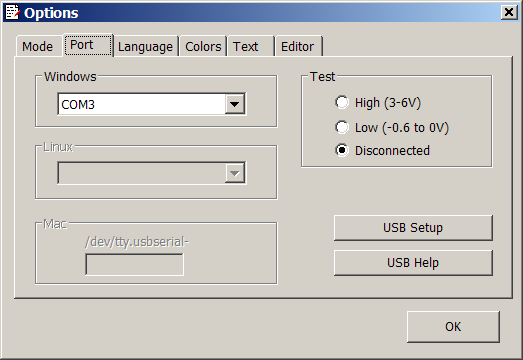
Now switch to the Mode tab and select microcontroller type PICAXE-08M. Hit Firmware button. In a few seconds a dialog will appear telling you if you AXEpad can communicate with the microcontroller or not.
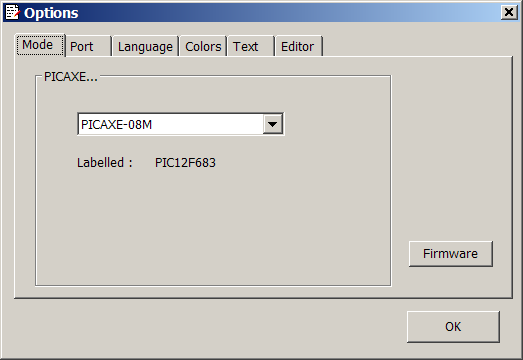
If the dialog you see will say that AXEpad can’t find the hardware one of a few things could be a problem:

- The port you selected is not the one connected to the microcontroller. Try another port. You can also open device manager, find what port is associated with the USB-to-RS232 adapter just to be sure.
- The programmer scheme is assembled incorrectly. Verify that it matches the breadboard diagram above.
- The batteries are running out of juice. Check the battery, replace if necessary.
- If the microcontroller is not new there is a probability that the code loaded into it messed up with frequencies and you need to hard reset the microcontroller. To do that
- make sure the port is set correctly (use device manager as described)
- hit ok to close the options dialog
- disconnect power from the programmer
- click on Program button in the toolbar
- when the programming dialog appears connect power to the microcontroller again
- if programming went well – you’re done. If not, … well, maybe the microcontroller is fried? It is a delicate IC and it is not that difficult to make it unusable. For instance static electricity from your sweater can kill it. For this reason always ground yourself (touch something connected to ground with bare hand, for instance) before working with the IC. Ideally you need to keep yourself grounded with a special strap at all times when you’re working with the IC.
This is how the Firmware dialog looks like when you chose right port, it is connected to correctly assembled programmer and microcontroller is working fine:
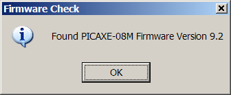
Hardware Found Everything is ready to send the code to the microcontroller, so hit the Program toolbar button. New popup window will appear and tell you what’s going on. It looks like this:

Programming PICAXE The programming process will end with one of these two dialogs:
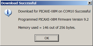
- Success – means that the code was successfully sent to the microcontroller. It also means that you assembled the programmer correctly. With the code you copypaseted the RGB LED should start changing colors just like the locket did in the beginning of this video. At this point your programming job is complete.
- Error. Typically this dialog looks like it is shown below:

PICAXE Programming Error The reasons for the programming error are essentially the same as described above.
If everything went well then you will see the LED start changing color like in mood lamp.
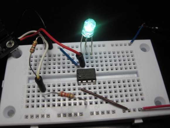
Program is Working! The code you just uploaded is actually pretty tricky. What it does is called software PWM and it is discussed in more detailed format in my personal blog at https://andrey.mikhalchuk.com/2011/06/23/controlling-rgb-led-using-picaxe-08-basics-of-software-pwm.html

Andrey Mikhalchuk's Blog So the prototype works pretty well, it’s time to pack everything into the locket. And here we face another challenge: the microcontroller, the LED and pair of very small batteries won’t fit the locket! And we also need to include some kind of switch with all this.
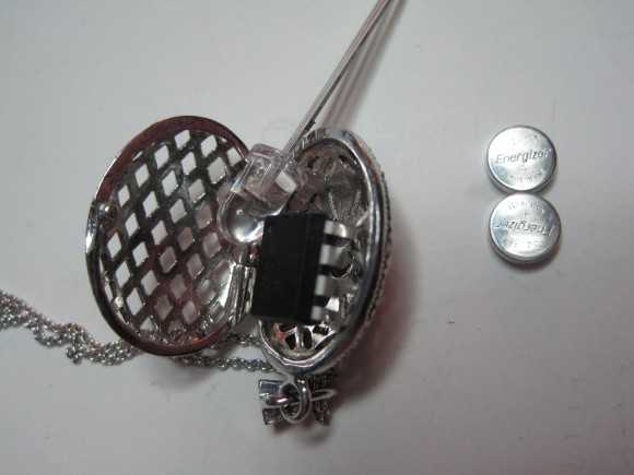
Too Big to Fit As you can see on these pictures it’s not trivial to fit all the parts into the tiny locket and requires some work with a file, sidecutters and sanding paper. Remove all platstic you can from the LED without compromising its integrity. I ruined 3 LEDs before getting satisfactory result, but check our how small the LED became comparing to the original one. It also became diffused, thanks to sanding paper.
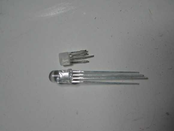
Miniaturized LED The microcontroller also can be trimmer from both sides. You can remove approximately half mm of plastic from each side. Before doing that make sure you mark the the first pin by making a notch on the key side of the chip. The original marking will be gone withexcessive plastic. This procedure essentially turns DIP package into a SOIC-like package.
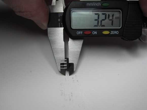
PICAXE-08 Before Miniaturization 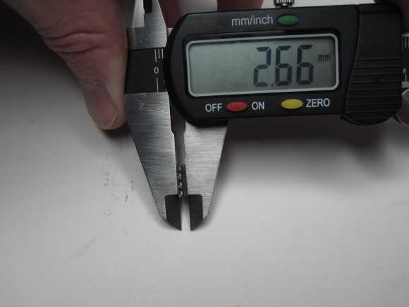
... and After Finally I added two contacts for the battery and wrapped everything with heat shrink. The white paint you see on the picture reflects the LED light making it more even.
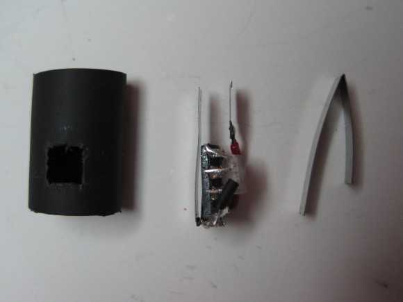
Without Heatshrink 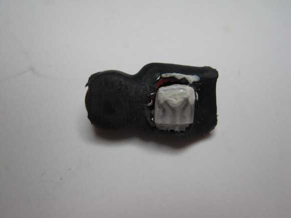
Fully Assembled: Top View But what about some kind of switch for this device? I cut the wire connecting the battery to the microcontroller and exposed its ends. The locket is made of metal, so to turn the microcontroller on you just need to put this package inside the locket. The locket will shortcut the wires and let the current flow to the microcontroller.
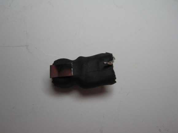
Bottom View with Contacts Exposed Here my project ends and yours starts. You can play with different parameters or implement your own color changing scheme. In fact in one of the future episodes I’ll show you how to make jewelry interactive using this approach. Keep watching!



Just curious why you didnt get an SMD version of that PIC?
A Lot smaller without all the work…
Also, I would have gone for a single CR2032 battery, the 3v lights most leds quite well.
Pyrofer,
thanks for the suggestions.
– I decided to go with PDIP because it is easier to solder and it can be used with the breadboard. I wanted this project require as few skills as possible and soldering a SOIC could be a challenge for beginners. Another thing one can do is use SMD LEDs, they are also much smaller but, again, they are more difficult to solder.
– CR2032 is just too large for the locket I used. Even CR1620 didn’t fit inside. It’s a good choice for larger jewelry though.
Andrey